Budget astrophotograhy

We took a Nikon D5100 and Sigma 150-500 f5-6.3 to a designated dark spot in the Cotswolds. I’ve imaged Jupiter with this lens from South Manchester, at 5.1AU distance, so I figured I could get photos at least that good from a dark site, with Jupiter at 5AU distance.

Well here is Jupiter, with some motion blur due to my strong and stable tripod:

Just out of curiosity, I also tried to get some shots of Saturn. Saturn is ~10% smaller than Jupiter, and was also almost twice as far away (9AU distance), so I didn’t expect to get any detail – maybe an oval would be the best result I could manage at 500mm with glass optics?


(Click for viewer)
 

In the creative and poetic words of Donald Trump: “Wrong!” – Saturn’s rings are visibly distinct from the planet itself, although no moons were resolved in any of the photos I took.

That’s Saturn and rings at 9AU distance, on a D5100 body and with a Sigma 150-500mm lens, processed with RawTherapee.

Nice. Unfortunately 9AU is the closest Saturn gets so I’m unlikely to get a better photo with the budget equipment although I’ll take some with a 1metre f/5 Skywatcher when I get time. Jupiter’s closest approach is 4.5AU (10% closer than so I’ll also try Jupiter again with the telescope when it’s at closest approach – the Skywatcher should be able to resolve the atmospheric bands on Jupiter too.

Effects are evil

RAW, optical filters, post-processing: Haters gonna hate

I often hear people criticising the those who use optical filters or who post-process photos, the brainfart usually goes something like “the photo should capture how we see the scene” or some other dogmatic nonsense along those lines.  These people usually say that we should just shoot on automatic, and publish the resulting JPEG image as it comes off the camera instead of using manual mode, raw sensor data, and a post-processing workflow.

This is nonsense for several reasons, the best probably being that the camera doesn’t see the scene even remotely the same as we do.  They have a very wild colour range which is nothing like that of the human eye, which is why there are strong infra-red filters built into most camera sensors or lenses.  When you shoot a JPEG in awesome mode “automatic mode” you aren’t taking a picture “without effects”, you are merely having the camera apply effects automatically based on its “best guess” of how the scene looks to a human.  Should the camera guess wrong, you have no way to fix the image manually (without compromising quality significantly) since you have no RAW file.  Congratulations.

Aside from dynamic range expansion, white balance adjustments, distortion correction, noise reduction and the other usual “automatic” effects used by people who think that they take photos with no effects, there is another idiotic flaw in their reasoning.  Colour and intensity perception isn’t uniform amongst humans, and also varies considerably for each individual, depending on their recent visual experiences.  That is to say, the human visual system exhibits hysteresis.

Scotopic and photopic vision

During the day, the eye uses colour-sensitive cone receptors to detect light, known as photopic vision.  These are mostly concentrated in the central “high-definition” region of the retina, the macula lutea.  After half an hour or without any bright light, the eye transitions into “night-vision” mode or scotopic vision, where extremely sensitive rod receptors are used to detect light, and the colour-sensitive cones are almost completely shut off.  Rods are most sensitive to blue and violet, with very little sensitivity to hues from green to red, so colour perception with rod-vision is considerably reduced* compared to cone-vision.  Rods do not occur as densely anywhere in the retina as cones do in the macula, so rod-vision is also of considerably lower “resolution” than cone-vision.

* Colour vision during scotopic vision is only possible because the cones don’t completely shut off.

Different eyes see different primary colours

Colour perception also varies from person to person.  We typically have three types of colour receptor: L-cones, M-cones and S-cones.  There are different genetic variations of each of these receptors.  Hence, different people may have slightly different primary colours.  The L (“long”) receptor pigment is located on the X chromosome, so women have two red pigments encoded in their DNA.  In some rare circumstances, this can lead to two separate red receptors being present – and thus such women have vision with four primary colours.

Silicon sensors in cameras see a considerably different set of primary colours than human eyes do, and have wildly different response curves compares to cone receptors.  They are very sensitive to infra-red, hence your camera typically has an infra-red removing filter built into the sensor (or the lens on comact cameras).  Removing this filter from a compact camera results in a cool night-vision camera.

A variety of other causes can affect the way that a single individual perceives colours too, such as calcium intake and potassium intake.

Even we don’t see colours “as they are”, our perceived colour space is extremely degenerate

Pure monochromatic yellow light appears the same** as a carefully measured mix of red and green light, since we have no yellow-sensitive receptors but only perceive yellow due to the way it stimulates both red and green receptors simultaneously.  Colour-mixing effects like this can be used to create effects, sometimes used in low-budget plays and gigs.  A pigment which responds to pure yellow but not to red or green, will appear yellow under pure yellow light, but black under a mixture of reasonably pure red and green light.  Hence, performances that cannot afford projectors or stage lasers can still have some animation, appearances, disappearances, and flashing in their backdrop with clever use of light filters and simple DMX programmes.

** The white on the screen that you are currently looking at is actually a mix of red, green, and blue light.  Take a close look at the screen with a magnifier to see the pattern of red/green/blue sub-pixels that have been tricking your brain into thinking that things on your screen were yellow/white/cyan/purple for all these years.

Summary

Unless all your digital photos are a mess of green and purple, you are using effects and some kind of post-processing workflow whether you realise it or not.  That “automatic” mode isn’t a “no effects”, but rather a “guess some effects and hope for the best” switch.  Shooting JPEG has only one advantage over RAW: Smaller file size.  While the “automatic” mode on modern cameras is extremely good at guessing the levels of each effect that it applies, it is rarely as good as a human choice.

While you’re thinking about how much science has ruined your views once again, why not also calibrate your monitor so you can get the most out of those [thirstylink linkid=”1340″ linktext=”£500 gold-plated HDMI leads”] that the TV shop told you were “totally necessary”?

Aura

I think I just created the world’s most awesome USB gadget.  Probably the biggest and most expensive too.  When I say “created”, my part was the light source and the power supply…  The rest (i.e. the actual Aura painting on the massive canvas) is the work of a very talented upcoming artist, save the painting in the gold frame which is a family creation and heirloom.
Oh, the smaller poster on the wall, that’s my creation…

Aura, running off a crappy old Dell laptop via USB

Although I was lucky enough to see the artistic development of the piece from an idea in a sketchbook, through experiments with various media, software mockups, and ultimately: the final canvas, I shall leave commentary on the motivation/meaning/development of the Aura painting to the artist.  I will describe the design and construction of my solution to the lighting and power problem which this artwork originally posed.


Rather than having lots of tacky little LEDs poking through the canvas, the artist chose to use fibre optic cable to provide the starlight.  Behind the canvas, the fibres are bundled tightly together into a ~10mm cylindrical end.  Originally, a pocket torch was fixed to the end of the fibre bundle in order to provide light, however the battery life was poor as was the brightness and colour temperature.  Additionally, the brightness decayed noticabley as the battery drained.  If the piece is to be exhibitioned for hours or displayed in a gallery for weeks, then the backlighting must provide a consistent, bright, “cool-blue” white beam requiring absolutely zero maintenance for days or weeks.  Maintenance includes replacement of batteries and worn-out light bulbs – so an alternative lighting technology is required.  This is the problem that I was approached with.

[ TODO: Nice illustration of colour temperature.  Eventually. ]

My immediate thought was semiconductor solid-state lighting – a laser or some LED.  Lasers, while fun and fairly predictable to work with, are typically not used for providing light that is both continuous and wide-band, so that left LEDs.  Rather than use multiple LEDs and a reflector cone/cylinder to pass the light into the fibre, I used a single high-intensity white LED.  Beyond a certain voltage level, the brightness would vary little with increasing voltage however the colour temperature could be finely controlled within this range.  This meant that I could select a colour temperature, provided my power supply provided a consistent output for the LED.  I should warn you that after looking directly at the high-intensity LED for half a second (while testing it with a 3.7V Nokia brickphone battery) my eyes took around half an hour to recover from the glare, after which I had a little short-lived fun strobing the LED at my brother – who responded with words that cannot be shown on this site…

My first thought for a power supply was to use a 7805 linear regulator plus a diode to reduce the voltage further, however this requires at least eight volts input to operate, and for a three-to-four volt output – it will waste at least half of the power, generating considerable heat (which would damage the artwork) and draining batteries too fast.

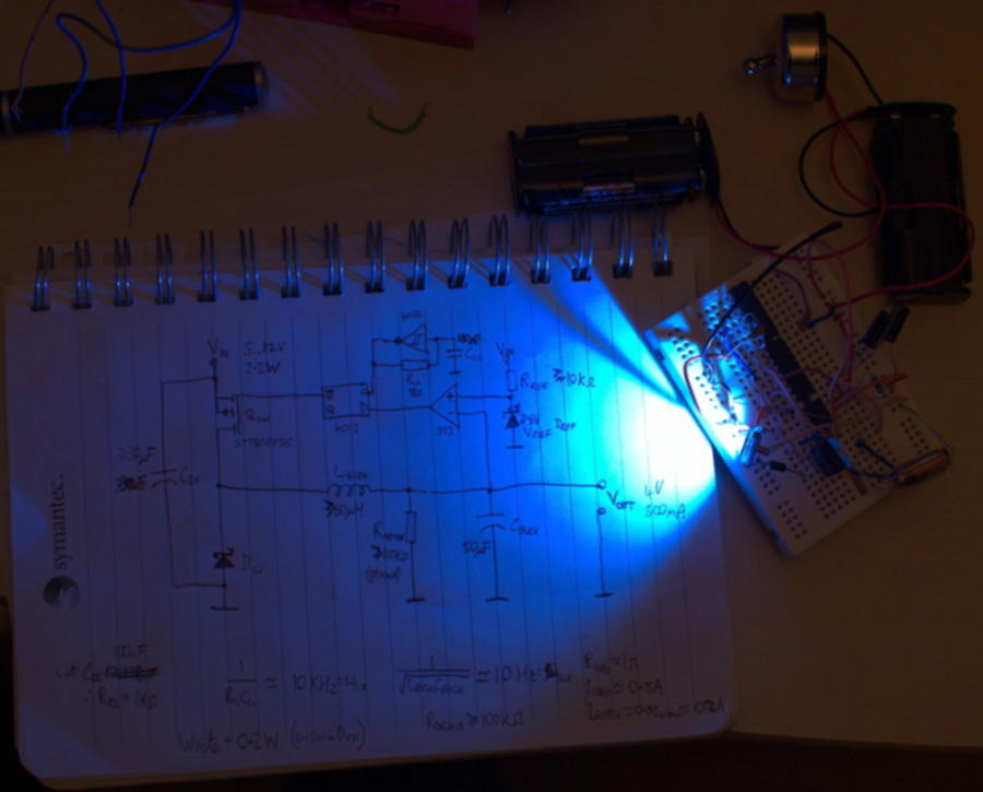
Having recently designed and built a variable speed, bidirectional motor controller using a PWM-driven H-bridge, I decided to use a switching power converter instead.  Some quick research showed that ICs are available to do most of the work for me, but where’s the fun in that?  I found a nice online lecture series titled “Introduction to Power Electronics“, provided by University of Colorado Boulder which explained the theory and mathematics of switching converters.  After a few hours of solid lectures, I designed my own buck converter and posted the design to Stack Exchange to get critical feedback on it.  I only need around 3.5V / 300mA maximum to drive the ultrabright LED however I designed the converter to supply 3.0-3.9V / 2A so that I would have headroom for any other electronics that might be added later.  Given the inductor that I eventually chose, the current should not exceed 1.4A in the actual final build.

2013-11-25 15.48.45 - clip

Had I waited a few more days before prototyping and building my design, I’d have used the following design which was produced using the later advice received on Electronics Stack Exchange:

Aura SMPS

Maybe replace the Schmitt-triggered inverter/R/C oscillator with a 555 too…

However I wanted to do this quickly as I had other projects pending at the time, so rather than waiting days for critical comments and recommendations to accumulate, I settled for a slightly simpler and less efficient design in response to the first few criticisms received on Stack Exchange.  I stuck with the incredibly unstable Schmitt-triggered inverter for the clock generator, as the instability will result in a wide frequency range.  The electromagnetic interference generated by this converter will be broadband as a result of this, so there will be considerably less interference at any particular frequency compared to a converter with a stable, narrowband clock generator.

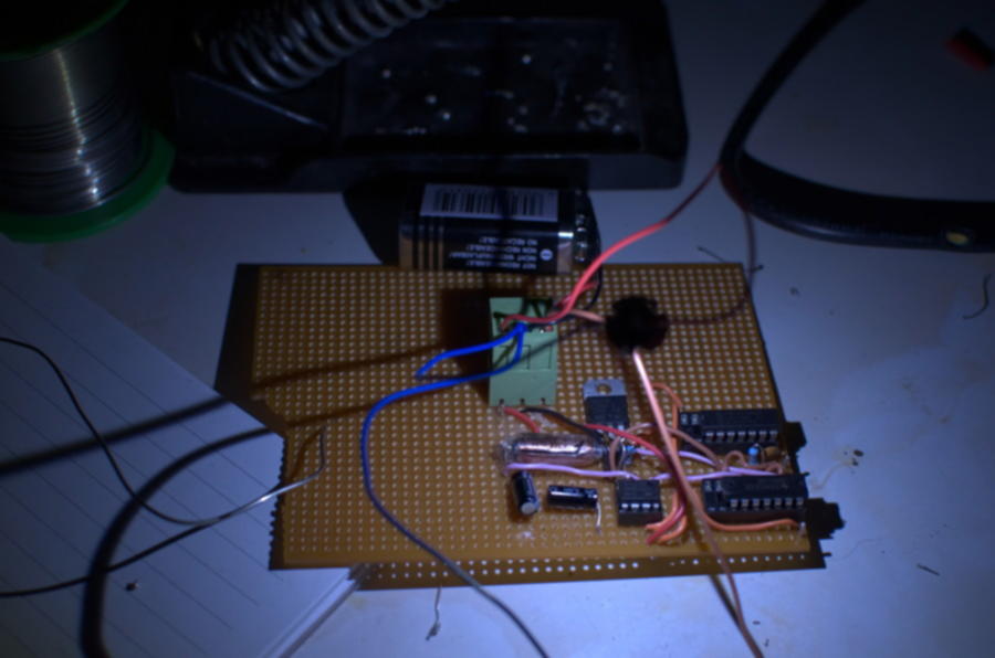
I hate breadboards, but decided to prototype on one since this was my first switching power converter, and probably wouldn’t work.  After a trip to my local components shop, and an hour of assembly, to my surprise the converter worked!  I fiddled with it a little to see how it would respond to output shorting or to a higher impedance (1kΩ) load.  For the former, the STP80PF55 transistor easily handled the strain (ID(max) = 80A), and the inductor didn’t heat noticeably despite only being rated for 1.4A continuous current.  For the latter, the converter still provided a stable voltage with no noticeable heating of any components, although the converter’s efficiency dropped below 50%.

Breadboard build that actually works first time!

After this, I moved onto the “fun” part – figuring out how to translate this design to a circuit board.  As I have yet to find any stable electronics design software that installs and runs on Linux, I did the layout and routing manually. Three revisions later, I put the components onto a matrix board and started soldering.  I would have ideally used a purpose printed board, but that required: (a) a computerised design; and (b) waiting for the board to arrive in the post.  My last tripad board was taken by a computer vision and robotics project, Smartie, so I was stuck with a matrix board that had no copper on it at all. Time for some retro old-school point-to-point soldering!

Aura SMPS PCB

The only light in this image is from the LED itself

This, combined with my inefficient manual routing resulted in the power supply being the size of a credit card and a centimetre thick. Still though, it was small enough to fit behind the artwork.  From the unit extends two power connectors which allow it to be driven either by a 5V USB smartphone charger or by a PP3 9V battery, the latter of which should provide over a day of consistent lighting while the former could provide eternal lighting if a mains socket was nearby.

_DSC0025


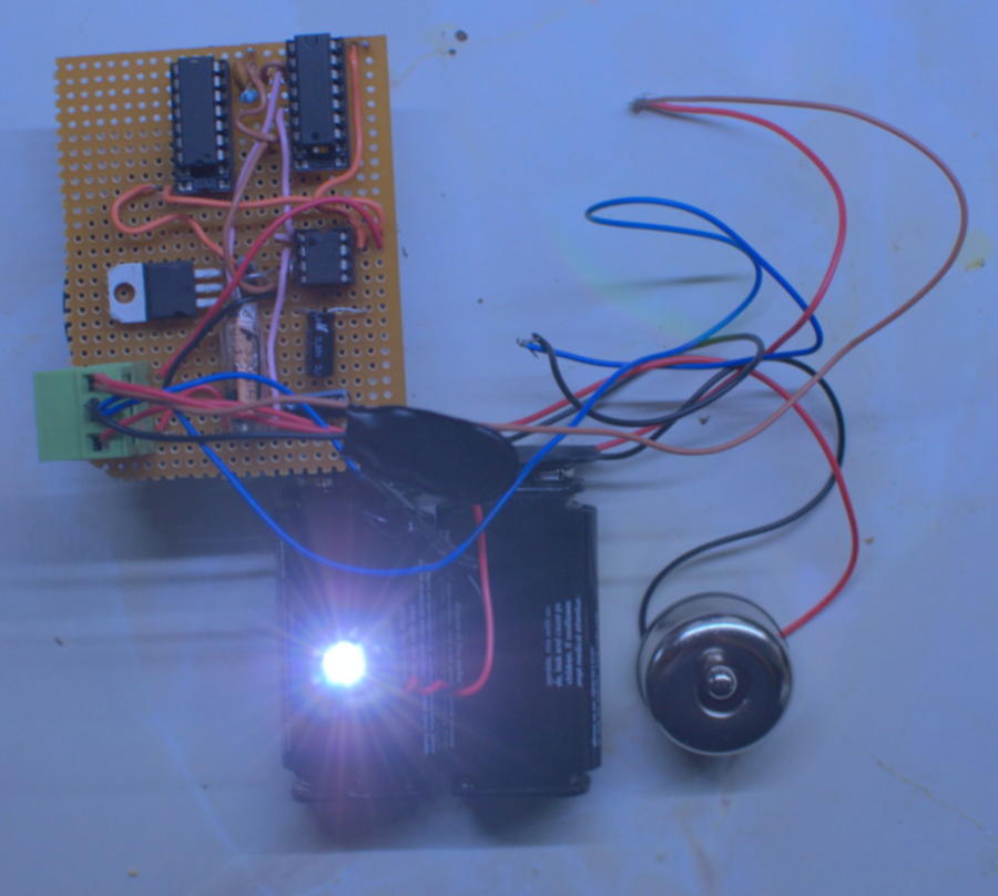
The unit connects to a daughterboard which the power LED is screwed into, allowing the power supply to be mounted a distance from the fibre optic bundle.  I initially planned to use an 
epoxy resin cone coated in aluminium foil to funnel light directly from the LED into the fibre, without crossing an air interface at all – this would provide high efficiency usage of the light.  During testing however, the brightness was more than sufficient despite a centimetre air gap between the LED and the fibre bundle.

Although the LED heats up considerably during prolonged use, it radiates almost no heat in comparison to a conventional light bulb – so does not heat its surroundings unless it comes into contact with them.  Despite this, I plan to cut a small spacer, to ensure that the canvas never comes into contact with any hot components.

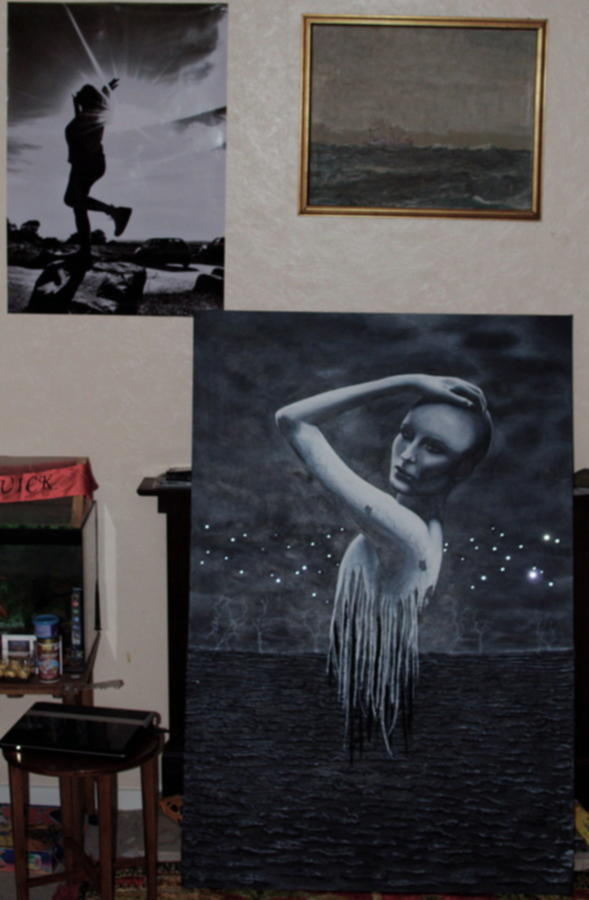
Here is the finished piece so to speak, “Aura” illuminated via a phone charger cable, powered by a laptop:

Aura, running off a crappy old Dell laptop via USB

And for the humour value:

USB Aura device detected

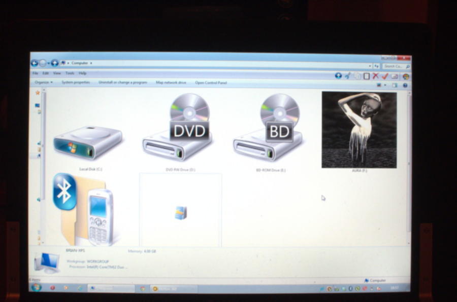
Windows displays a half-finished image of the painting as the device icon. As usual, Windows is out-of-date…

As a possible improvement, we considered making the lights flicker too, but they had to flicker independent of each other to avoid looking like some cheesy modern art crap.  Various ideas appeared on the table:

  • Attach a mobile phone vibrator to the LED daughterboard, so that the LED wobbles above the fibre bundle.  Creates noise and wastes power though.
  • Two LEDs on the fibre bundle, alternately driven by a multivibrator with lowpass filters on the outputs.  Will still look like some tacky modern art crap.
  • Vibrate a piece of string over the end of the fibre bundle.  Cheap, low power, but likely to jam or otherwise not work properly.
  • Use a clock mechanism to efficiently spin a dotted/stripey filter over the fibre bundle to create a seemingly random flickering of individual fibres – Jackpot!