
At the start of the corona lock-down in 2020, I decided to use the time to get back into a hobby from when I was ~14 years old — classical guitar. I figured that rather than ordering a high-end guitar straight away, I should order something cheap (but still playable) to start with, then reward myself for progress with something higher-end nearer the end of the year.
Once the guitar arrived, I realised that I needed to find space in the flat to put the guitar, and I needed a stand for it. The guitar came inside a large cardboard box, inside another large cardboard box, so I decided to recycle that box into stands for my guitars.
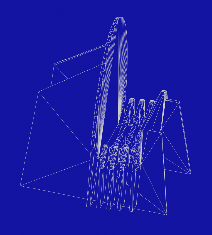
I started imagineering what the stand might look like, trying to keep the design simple while minimising the amount of material and components required. Thanks to Neuralink Blender, I was able to transfer this from my brain to the computer so I can share it with you via this link and in lower-quality at the end of this page.
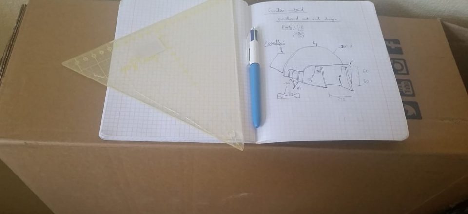
I made a few quick sketches of possible designs, and settled on this design. This design in turn is currently settled on top of the box that I’ll be converting to guitar stands.
FreeCAD
For my hobby (i.e. unpaid) projects, I restrict myself to free/open-source tools wherever possible, so I designed the stand using FreeCAD:
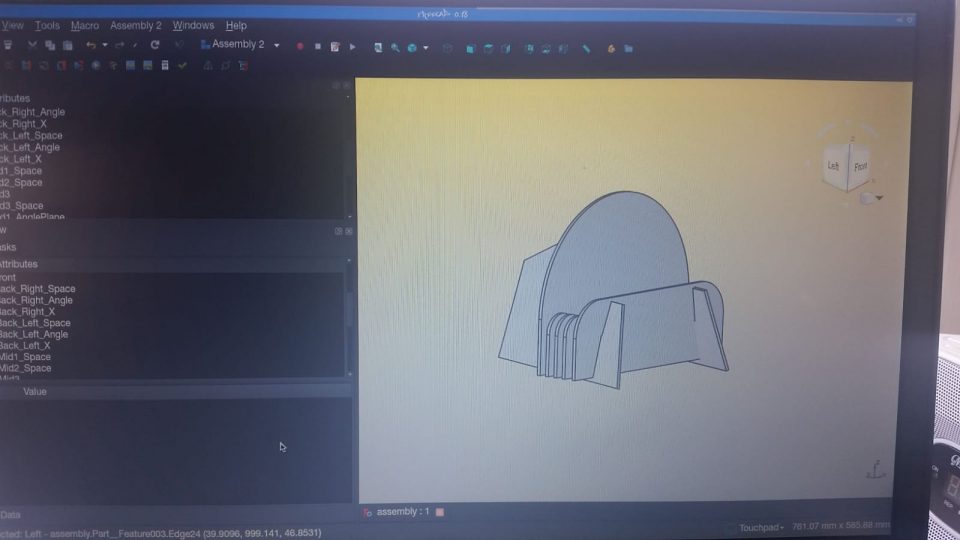
FreeCAD is similar to most other CAD software in many ways – a bit rough and ugly, crashes at least twice per day when working on anything particularly complex (which this stand is not). But unlike other most CAD software, it’s free and supports “Blender-style” viewport navigation which makes it much nicer to use vs. having to switch between two navigation styles all the time.
The stand consists of four unique flat components, seven components total per stand. The sketches are shown below. The red constraints are driving constraints and the blue constraints are reference constraints.
You may wonder why I seem to have so many reference constraints here. That will become apparent next.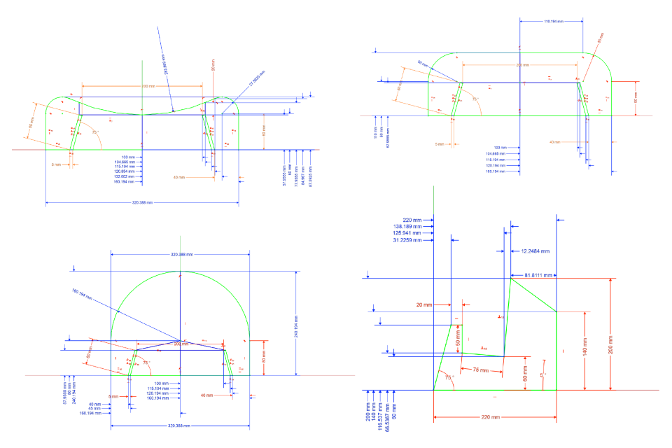 As I live in Estonia, I don’t have a printer. Most stuff here happens online, there’s no need for paper and ink most of the time. The rare time when I do need to print some documents, I’ll walk across the road to the print shop and pay 50¢ for them to print it, instead of owning some crappy home printer that always finds some bullshit reason to refuse to print whenever you need it the most. But we’re in lock-down – the print shop is probably closed. Even if it isn’t, this printing isn’t exactly “essential”.
So I can’t use a “2D printer” to print these sketches to make templates for cutting the cardboard. My 3D printer is in another country otherwise I’d just attach a pen to it then have it trace out the part outlines with a SVG→DXF→Gcode pipeline. My (prospective) CNC milling machines haven’t been purchased yet. I’ll need to make the templates by hand, and cut them by hand.
Old-school Drafting
So rather than calculate vertex positions manually, I used reference constraints to have the CAD software measure them for me. Then I marked these coördinates on some paper and linked them using a straightedge.
The curved parts of the sketches still remained though. I marked out points at 30/45/60° on these curved segments, linked them faintly by straight edges, then drew curves through them by hand. Finding 30/45/60° points is pretty simple. Taking zero-degrees to be x-wards and 90° to be y-wards (i.e. [x,y]=r[cosθ,sinθ]), we have the following easily-memorised trigonometric approximations:
| 0° = | ½(√4, √0) = | (1.00, 0.00) |
| 30° = | ½(√3, √1) ≈ | (0.87, 0.50) |
| 45° = | ½(√2, √2) ≈ | (0.71, 0.71) |
| 60° = | ½(√1, √3) ≈ | (0.50, 0.87) |
| 90° = | ½(√0, √4) = | (0.00, 1.00) |
Notice the increasing/decreasing integer sequences in the middle column, and the corresponding approximations in the right-column which follow the same monotonic behaviour. Just memorise the series “100 87 71 50 0”, then you can work out the sines/cosines of those angles by dividing the series by 100. Multiply the sine/cosine by radius of the arc, and you have the position of the arc (relative to the centre). A closer look at the uncut template shows this for the curved sections:
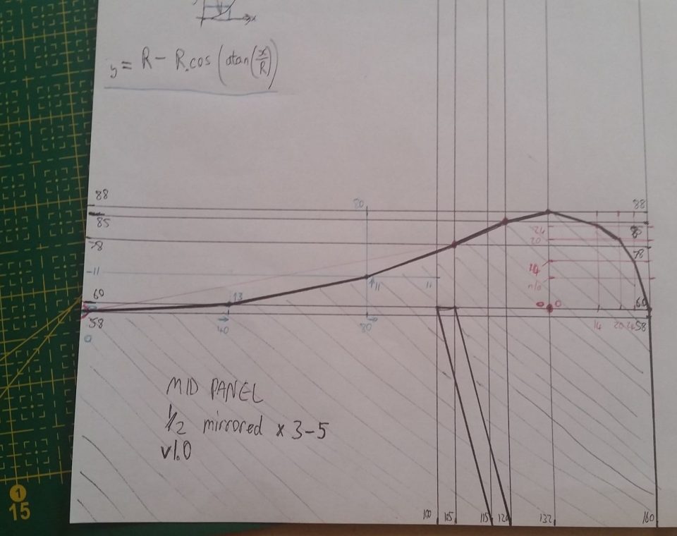
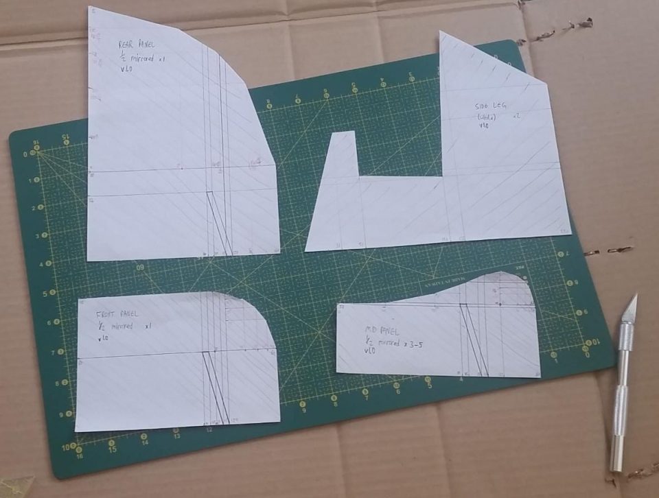
Since most of the parts have mirror symmetry, I only drew half of those parts on the template. I can draw half of the part onto the cardboard, then flip the template over, line it up, and draw the other half. Once happy with the drawings, I cut them out with my favourite scalpel.
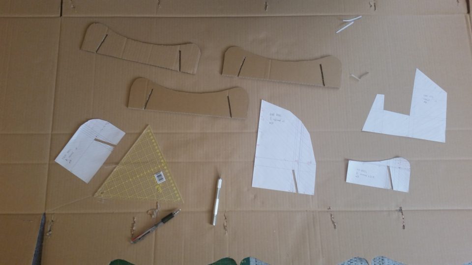
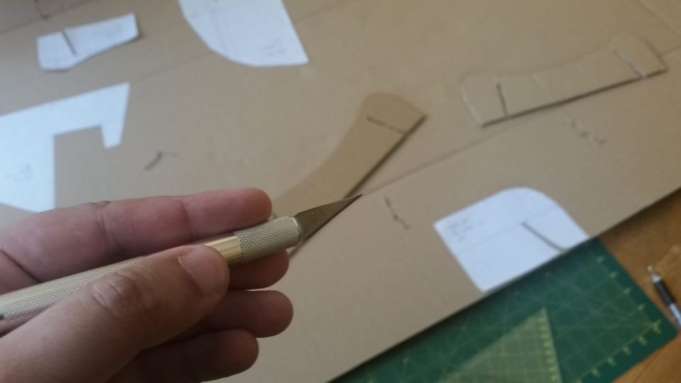
From there, I then traced the outline of each template / stencil onto the cardboard (mirroring where appropriate), to mark out all the parts. And then I cut them!
Assembly, integration, testing
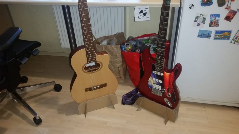
The assembly was as easy as expected – just slot the parts together. Once assembled, the guitar fit into the stand perfectly, and the resulting balance was quite stable.
I had enough cardboard left to make a second stand for my electric guitar, although that guitar is much heavier so the stand is less stable and probably won’t survive very long.
Cardboard easily produces just the right kind of sounds for this animation too ☺